Menu
EN
Menu
Production Equipments & Technological Processes Product Photos Magnetic Characteristics & Demagnetization Curves GBD Dimension & Coating

SINTERED SMCO

SINTERED NDFEB

MAGNETICS ASSEMBLIES

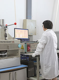
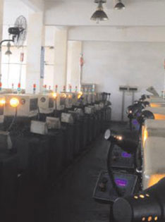
Manufacturing Equipments & Process Flow of Sintered NdFeB

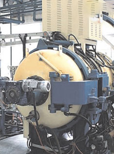
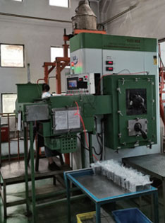
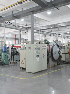
Advanced manufacturing equipments, automatic inspection equipments, high-tech R&D equipments

Compounding

Strip Casting

HD

Jet Milling

Pressing

Sintering

Magnetic Properties Testing

Machining

Inspection

Packing

SINTERED NDFEB
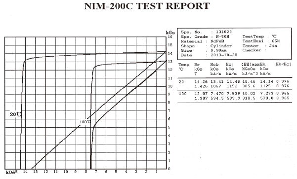
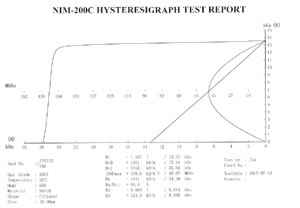
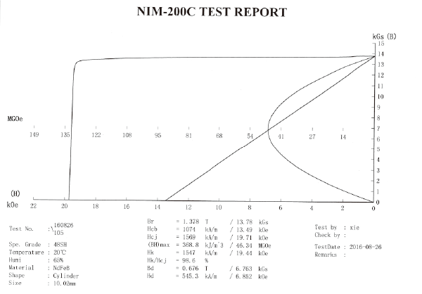
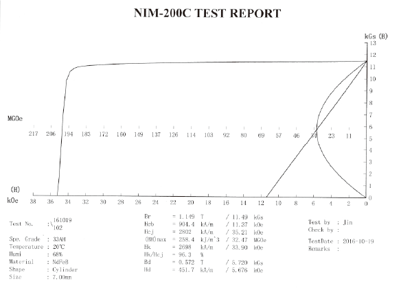
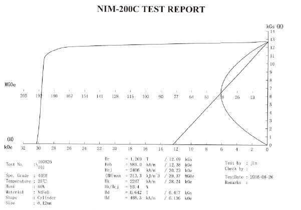
SINTERED NDFEB MAGNETIC PROPERTIES
DEMAGNETIZATION CURVES OF SINTERED NDFEB MAGNET
GRAIN BOUNDARY DIFFUSION

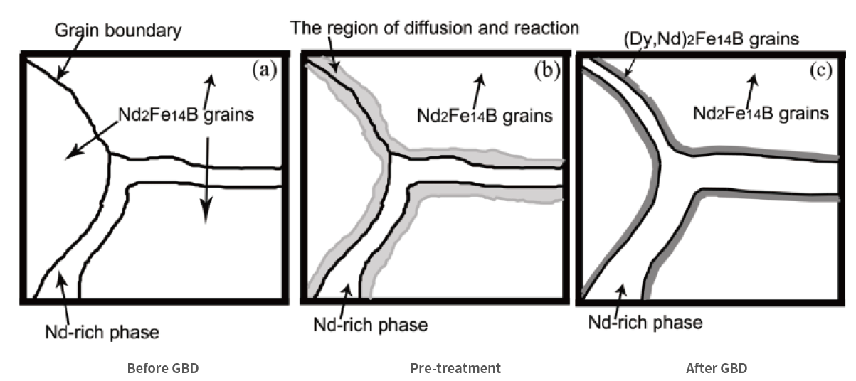
Grain boundary diffusion technology is to form a thin layer of Dy or Tb heavy rare earth on the surface of sintered NdFeB magnet sheet with thickness of 1-9mm by surface coating, magnetron sputtering, vacuum evaporation and electrophoretic deposition.After proper heat treatment and tempering treatment, the intrinsic coercivity of the magnet is greatly improved.It can reduce the use of heavy rare earths material, thereby reduce manufacturing costs. It can also produce high- performance magnet that can't produced by normal processes.

工藝流程

Manual feeding / automatic feeding

Automatic weighing

Workpiece heating

Automatic spraying (A side)

Automatic weighing

On line automatic turning material

Automatic heating

Workpiece heating

Automatic spraying (B side)

Automatic weighing

Unloading / automatic material receiving

Vacuum sintering furnace

Process flow chart Manual feeding / automatic feeding Automatic weighing Workpiece heating Automatic spraying(A side) Automatic weighing On line automatic turning material Automatic heating Workpiece heating Automatic spraying(B side) Automatic weighing Unloading / automatic material receiving Vacuum sintering furnace
Equipment
Illustration of grain boundary diffusion process
The coercivity of magnet with different thickness increases after grain boundary diffusion
Content of heavy rare earth in formula Product thickness(mm) Increase range of Hcj during grain boundary infiltration of Dy(kOe) Increase range of Hcj during grain boundary infiltration of Tb(kOe)
0 <4 4~5 7~8
0 4~8 3~4 6~7
>2% <4 3~4 6~7
>2% 4~8 2.5~3.5 5~6
Magnet shape Maximum machining size(mm) Minimum machining size(mm)
Block Rectangle:L200×W100×H40 L0.9×W0.3×H0.9
Square:L200×W100×H100
Ring D250×d150×H40 D1.5×d0.5×H0.5
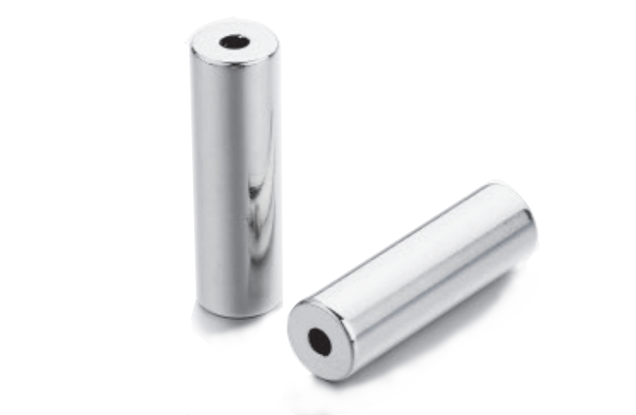
Cylinder D250×H40 D1×H0.5
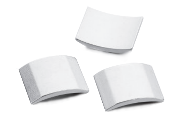
Arc segment L180×W80×H50 L3×W2×H1
Loaf L180×W80×H50 L3×W2×H1
Irregular L180×W80×H50 L0.9×W0.3×H0.9
Plating material Minimum part thickness(μm)
Ni 10
NiCuNi
Zn Zn 4
CZn 6
Ni+Sn 12
Ni+Ag
Epoxy 15

Remark 1 : Typical working environment generally refers to the room environment without dew.

Remark 2 : Minimum part thickness refers to the plating thickness in the main surface that can be contacted by the sphere of D20mm.

Remark 3 : The standard does not specify the maximum plating thickness(It is decided after discussion between the supplier and customer.).The maximum plating thickness should not affect the tolerance of final product size.

Remark 4: Minimum part thickness of the combined plating refers to the total thickness of the each plating layer.

Time to start to corrode
Plating material Time to start to corrode(h)
Neutral SST Damp heat test PCT
Ni(barrel plating) 36 500 36
Ni(rack plating) 16 500 36
NiCu+Ni(barrel plating) 36 500 36
NiCu+Ni(rackplating) 16 500 36
Zn Zn 24 72
CZn or Zn 48 72
Ni+Au 36 500 96
Ni+Sn 72 800 96
Epoxy 100 240

Remark 1 : Generally plating Zn does not apply to damp heat test, PCT and thermal shock test.

Remark 2:The result for neutral SST,damp heat test and PCT is based on general size,e.g.D10x3/D10x4,etc. When the magnet size changes, e.g. magnet weight>20g or <2g or irregular magnet including arc segment, the test result should adjust accordingly.